To Create a Panel Layout Later
If you wish to
create a control diagram or parts list first and use that to generate the Panel
Layout, use the following procedure:
- Ensure that the parts database records specify an appropriate panel layout symbol for each part number.
- Create a schematic or other diagram (hydraulic, pneumatic, etc.). You must assign a part number to each item if you later wish to select these items to place in a panel layout.
- Instead of a drawing, you can also create a parts list using the BOM Explorer in the Project Manager.
- Create a drawing page for the Panel Layout. When you create the page, use an appropriate scale factor in the Scale Factor field.
-
Set the software's
Drawing Mode to
Panel Layout Mode . You can select the drawing
mode when you create the page, or you can select it from the
Drawing Mode field on the drawing screen.

- Use the special drawing functions in the Design menu to create wireways, DIN rails, etc. You can do this at any convenient time while creating the layout drawing.
- Select the Insert Symbol By Device ID function to select and place the items from the diagram or parts list.
- The Insert Symbol/Macro dialog lists the items in the project having a device ID. You can sort the list by device tag, part number, etc., by clicking on the desired column heading. The Filter Devices fields on the left side of the dialog let you filter the list of displayed device IDs. By selecting the appropriate option, you can restrict the filter to Terminal/Plugs orDevices(non-terminals/plugs). Selector enter any combination of Installation, Location, Tag, Part Number and Function Text then select the Search button. Any device that match all of the entries is selected.
- Select one or more items to place in the drawing (hold down the <Shift> or <Ctrl> keys to select more than one item). Select the Place Symbols button. The software will prompt the appropriate layout symbol for the selected item (assuming this information is in the parts database). You will be prompted on the command line to Specify insertion point . Click at the desired position to place the layout symbol in the drawing.
- The Device Properties dialog will appear for the symbol that you are placing. The device ID fields are filled in automatically. Select the OK button to assign the ID.
- If the item you wish to place has more than one part number assigned to it, there will be a check box in the Multiple Symbols column. When you select this check box, the multiple part numbers are listed in a separate area at the bottom of the dialog. You can then select one or more of these for placement. If you do not select the check box, only the layout symbol for the primary part number will be placed.
-
If you select more than one item you can place them as a group.
You can make settings to determine how symbols are placed as a group. To do
this, select the
Group Settings link in the lower left corner
of the
Insert
Symbol/Macro dialog.
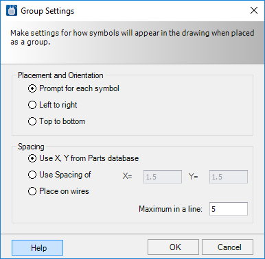
- Placement options allow you to select whether the symbols will be placed in a line from Left to right or from Top to bottom. If you choose Prompt for each symbol the software will allow you to pick a position for each symbol. If you place the symbols automatically in a line, the spacing options allow you set the distances between symbols. Use the X and Y fields to set a fixed distance between symbol reference points. Select Use X, Y from Parts database to use parts database height and width values to space symbols. You can also choose the Place on wires option to place symbols on existing wires, however this applies more to schematic drawings. Select OK to apply the group settings.
-
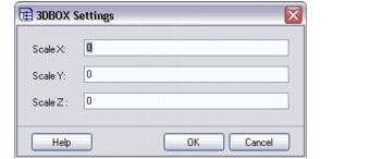
If you place an item with a part number that does not have a
layout symbol assigned in the parts database, the software will draw a box to
represent the item in the layout drawing using the dimension data for that
part. If the database does not contain dimension information for that part, the
following dialog will appear, prompting you to enter X, Y and Z.
dimensions.
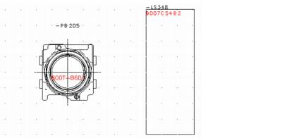
-
After you select
OK , the software will draw a box in the
layout using the entered dimensions. The box will be labeled with the device
tag.
- To select more items for placement, you can click the right mouse button or select the Insert Symbol By Device ID function again to return to the placement dialog.
- If the Show Place Devices in Current Drawing Mode check box is selected, any items that have been placed in the layout drawing will be marked with an X in the left column. If this check box is not selected, items will removed from the list as they as they are placed.
-
As with schematic drawings, you can choose to display or hide part
numbers, connection point text, etc., by selecting the appropriate buttons on
the display settings toolbar.

- If you wish to reposition any of the text associated with a layout symbol, right click on the text and select Text Position from the menu. You will then be able to move the text.